
My RNT-1510 opens the homebrew-project section: an adjustable 0–15 V supply delivering up to 10 A. Two knobs set voltage and current limit, with traditional analogue meters displaying both.
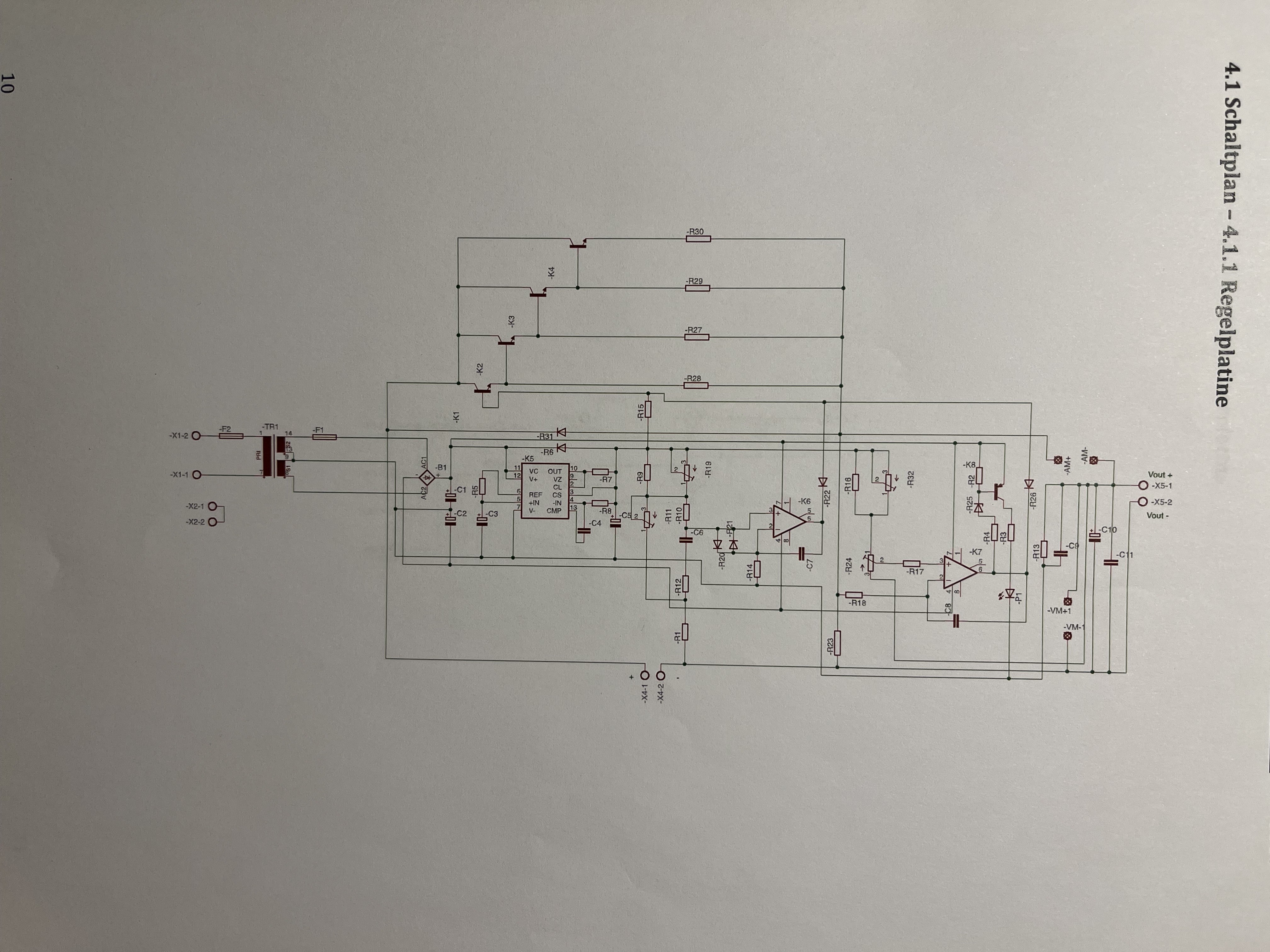
I wrote a service manual for it at the time. I still have the paper copy and photographed it for this article. Here are the description, parts lists and drawings. The front view and both schematics have been redrawn for this page.
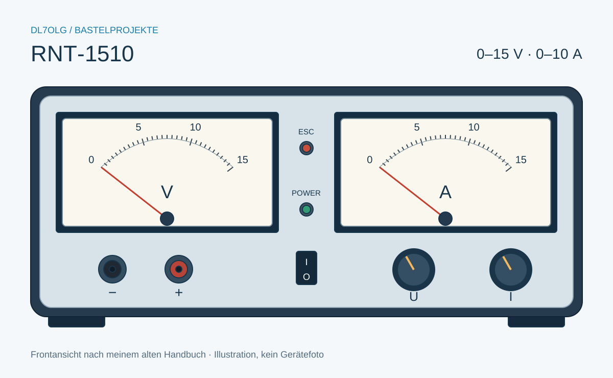
Specifications
| Property | Specification |
|---|---|
| Input | 230 V AC / 50 Hz |
| Output voltage | 0–15 V DC, continuously adjustable |
| Current limit / output current | 0–10 A, adjustable |
| Maximum output power | 150 W |
| Input current according to the manual | 0,05 A min. / 0,7 A max. |
| Protection | Electronic current limiting / short-circuit protection |
| Voltage display | Analog, 0–15 V |
| Current display | Analog, 0–15 A |
Construction and regulation
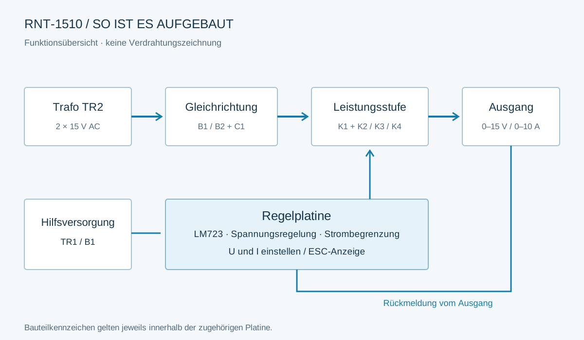
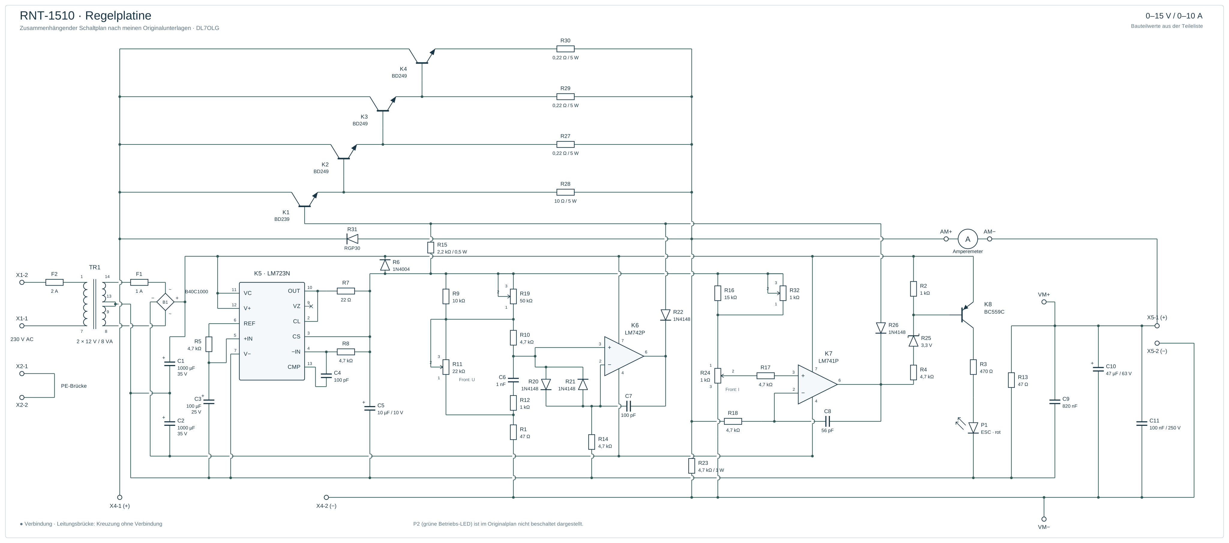
The circuit uses two boards: a rectifier board supplying the power stage, and the regulator board. The regulator also has its own supply with TR1 (2 × 12 V / 8 VA) and small rectifier B1. Reference numbering starts again on each board, so B1 does not always mean the same component.
Setting voltage
An LM723 compares the setpoint with output feedback. The 10 A does not pass through that small IC: K1, a BD239 driver, drives three BD249 power transistors, K2–K4.
The U control sets output voltage; my service notes identify it as R11. K6 is an LM742P in the additional voltage-control circuit. The conflicting entry in my old parts list has been corrected here.
Current limiting
The I control, R24, sets the current limit. K7 applies current limiting through diode R26. When the set limit is reached, output voltage is reduced.
The red ESC indicator P1 and transistor K8 belong to this circuit, described in the old manual as current limiting/short-circuit protection. Green LED P2 indicates operation.
Rectifier schematic
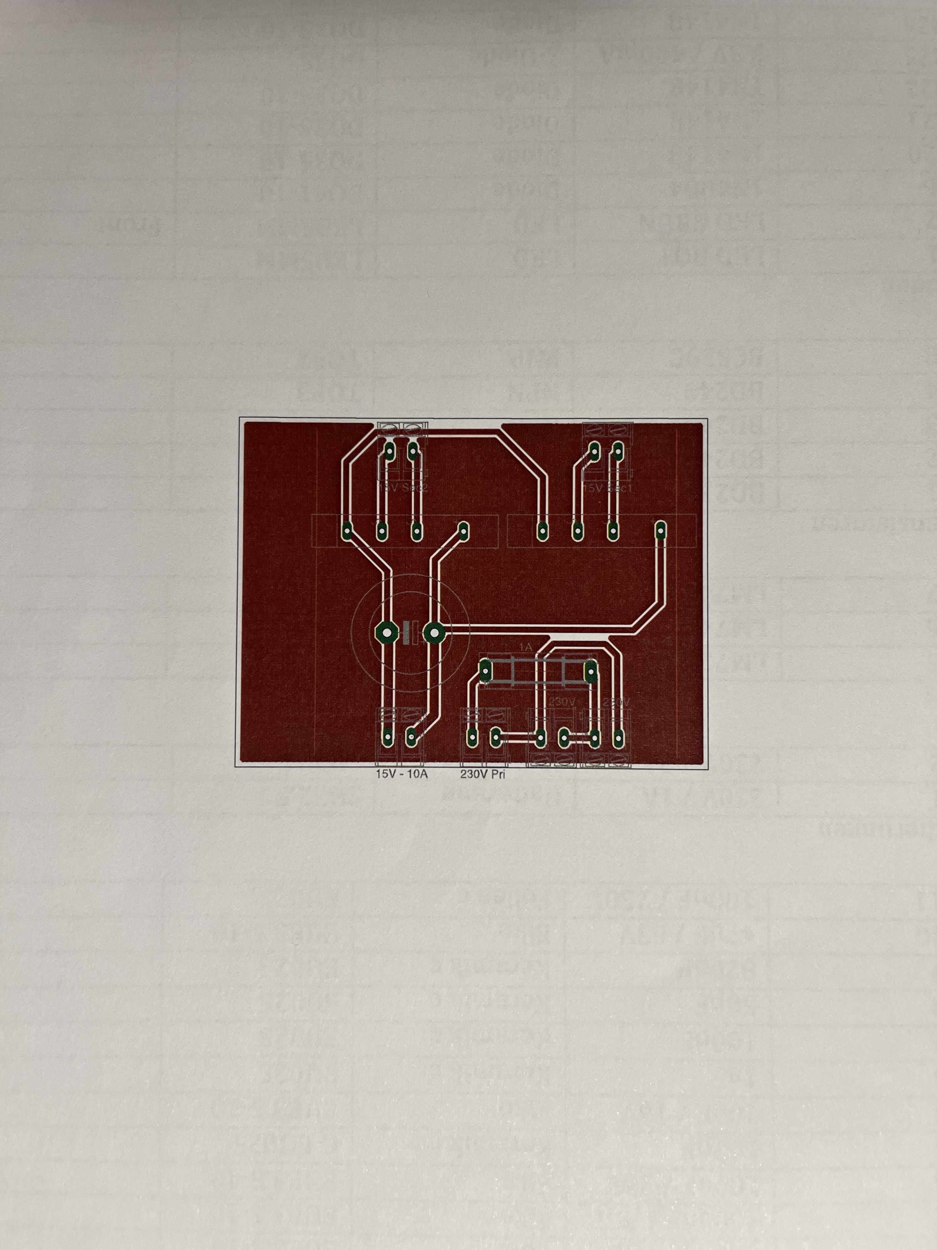
The drawing shows TR2 with two 15 V secondary windings, each feeding its own bridge, B1 or B2. Their DC outputs are paralleled in the original circuit. C1, 4700 µF, smooths the supply before it reaches the regulator board.
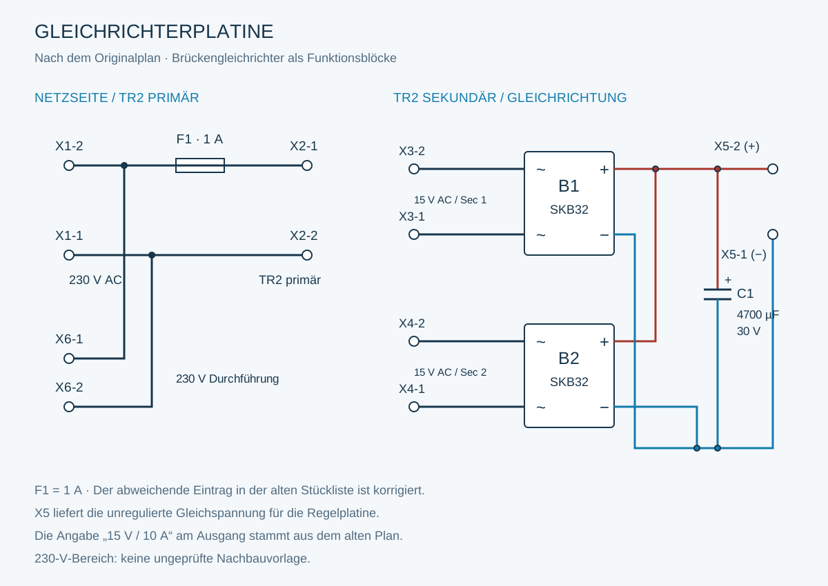
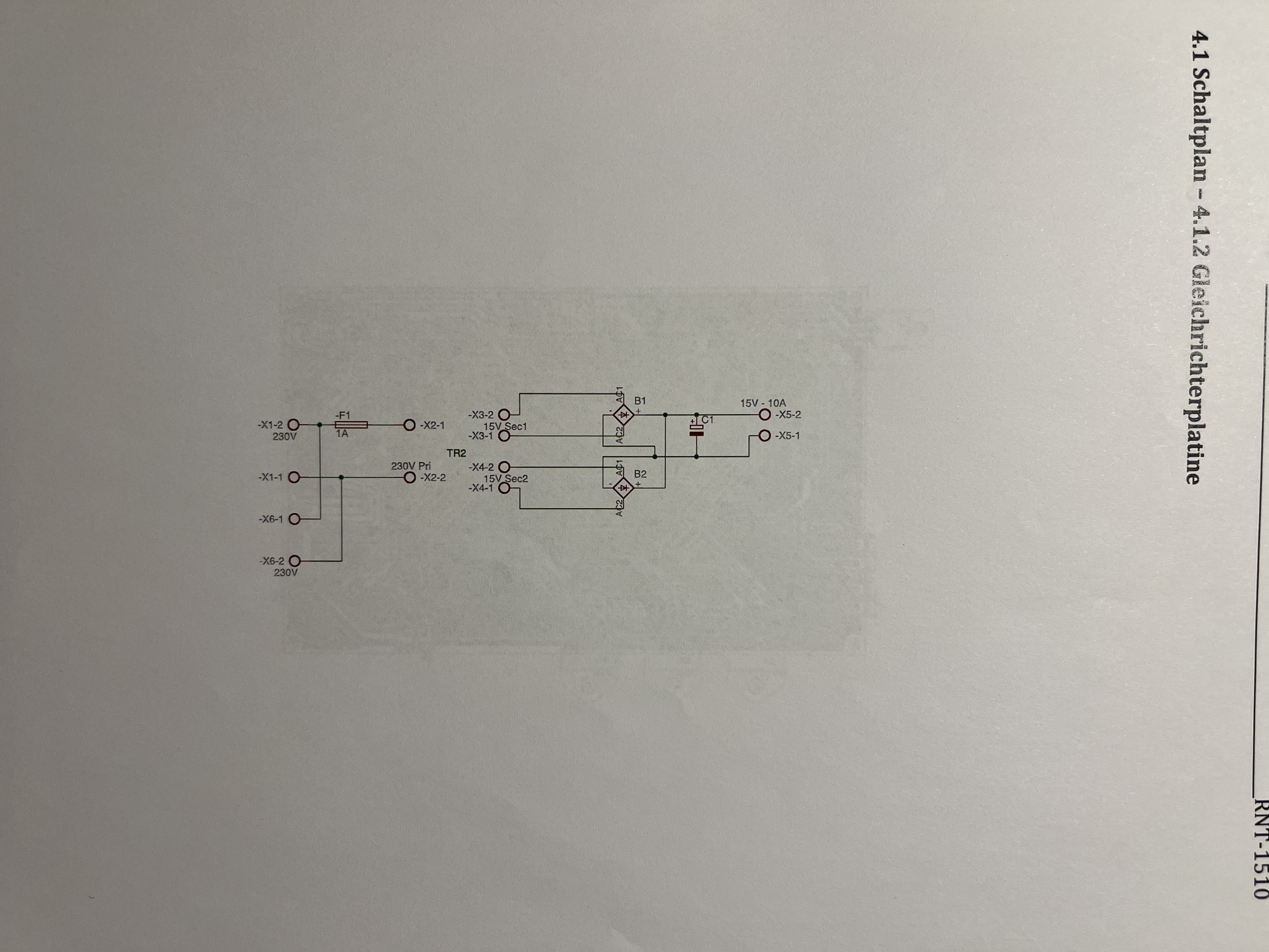
The old drawing labels this output “15 V – 10 A”, but this point carries unregulated DC. Adjustable output voltage is produced after regulation. Check terminal assignments: on this board X5-2 is positive and X5-1 negative. X5 has a different assignment on the regulator board.
Regulator board
The regulator schematic has been redrawn with component values from my list. All connections are continuous wires, as in the original.
Original regulator schematic for comparison
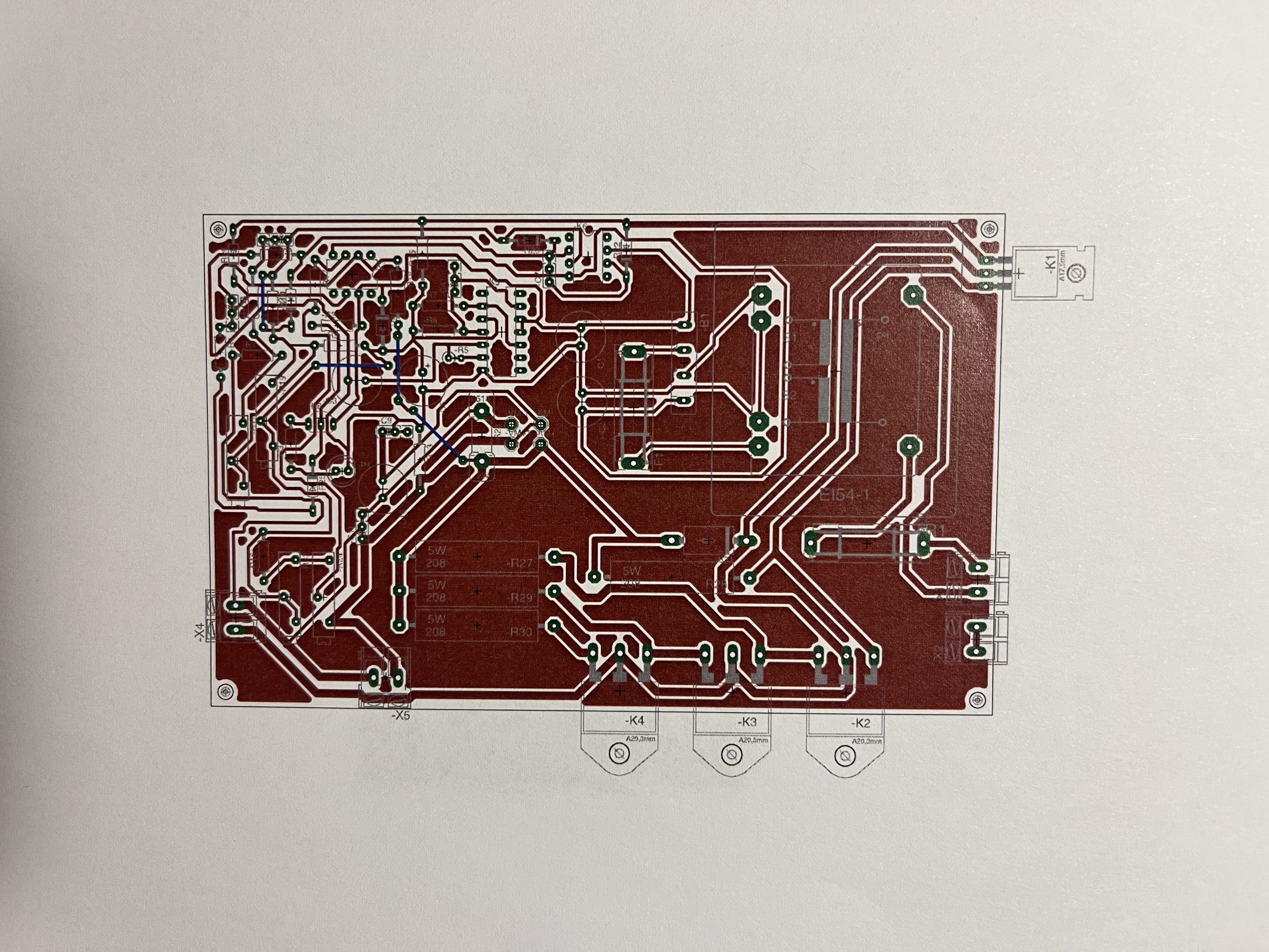
View both PCB layouts
Parts lists
I transcribed the legible entries below. Original reference designators are retained to match the drawings, including diodes sometimes designated “R”. Package descriptions also come from the old manual.
Regulator board
| Component | Value | Type / package |
|---|---|---|
| C1, C2 | each 1000 µF / 35 V | Electrolytic · EUE3.5-10 |
| C3 | 100 µF / 25 V | Electrolytic · EUE3.5-10 |
| C4 | 100 pF | Ceramic · C-EU025 |
| C5 | 10 µF / 10 V | Electrolytic · EUE3.5-10 |
| C6 | 1 nF | Ceramic · EU025 |
| C7 | 100 pF | Ceramic · EU025 |
| C8 | 56 pF | Ceramic · EU025 |
| C9 | 820 nF | Ceramic · EU025 |
| C10 | 47 µF / 63 V | Electrolytic · EUE3.5-10 |
| C11 | 100 nF / 250 V | Film · EU025 |
| Component | Type | Package / note |
|---|---|---|
| K5 | LM723N | DIL14 |
| K6 | LM742P | DIL08; part type corrected from the old list |
| K7 | LM741P | DIL08 |
| K1 | BD239, NPN | TO220 |
| K2, K3, K4 | each BD249, NPN | TOP3 |
| K8 | BC559C, PNP | TO92 |
| Component | Value / type | Package / note |
|---|---|---|
| P1 | LED, red | LED5MM · ESC |
| P2 | LED, green | LED5MM · Front / power indicator |
| R6 | 1N4004 | DO41-10 |
| R20, R21, R22, R26 | each 1N4148 | DO35-10 |
| R25 | Zener diode, 3.3 V / 400 mW | DO35 |
| R31 | RGP30 | DO201 |
| B1 | B40C1000 | Rectifier · FB15 |
| Component | BOM entry | Holder |
|---|---|---|
| F1 | 230 V / 1 A | SH22,5 |
| F2 | 230 V / 2 A | SH22,5 |
F1 is 1 A and F2 is 2 A. F1 on the separate rectifier board is also 1 A.
| Component | Value / rating | Listed package |
|---|---|---|
| R1 | 47 Ω | 0207/10 |
| R2 | 1 kΩ | 0207/10 |
| R3 | 470 Ω | 0207/10 |
| R4 | 4,7 kΩ | 0207/10 |
| R5 | 4,7 kΩ | 0207/2V |
| R7 | 22 Ω | 0207/10 |
| R8 | 4,7 kΩ | 0207/10 |
| R9 | 10 kΩ | 0207/10 |
| R10 | 4,7 kΩ | 0207/12 |
| R12 | 1 kΩ | 0207/12 |
| R13 | 47 Ω | 0207/12 |
| R14 | 4,7 kΩ | 0207/10 |
| R15 | 2,2 kΩ / 0,5 W | 0207/12 |
| R16 | 15 kΩ | 0207/10 |
| R17, R18 | each 4,7 kΩ | 0207/10 |
| R23 | 4,7 kΩ / 1 W | KP290 |
| R27, R29, R30 | each 0,22 Ω / 5 W | KH208-8 |
| R28 | 10 Ω / 5 W | KH208-8 |
| Component | Value | Package / function |
|---|---|---|
| R11 | 22 kΩ | CIP160C · Front panel, voltage |
| R19 | 50 kΩ | RTRIM43P · Trimmer |
| R24 | 1 kΩ | CIP160C · Front panel, current limit |
| R32 | 1 kΩ | RTRIM43P · Trimmer |
“0207/2V” for R5 is the package designation in the list, not a 2-watt rating.
| Component | Specification | Package |
|---|---|---|
| TR1 | 2 × 12 V / 8 VA | EI54-2 |
| X1 | 230 V input | AK300/2 |
| X2 | PE link | AK300/2 |
| X4 | Supply from rectifier board | AK300/2 |
| X5 | Regulated output | AK300/2 |
Rectifier board
| Component | Value / function | Package / note |
|---|---|---|
| F1 | 230 V / 1 A | SH22.5; 2 A entry in the old list corrected |
| X1 | 230 V input | AK300/2 |
| X2 | 230 V to transformer | AK300/2 |
| X3 | 15 V, secondary winding 1 | AK300/2 |
| X4 | 15 V, secondary winding 2 | AK300/2 |
| X5 | DC output | SKB32 · pitch 25,4 × 25,4 mm |
| X6 | 230 V feed-through | AK300/2 |
| B1, B2 | each SKB32 | SKB32 · pitch 25,4 × 25,4 mm |
| C1 | 4700 µF / 30 V | Electrolytic · EB25D |
Enclosure and front panel
| Part | Specification |
|---|---|
| Voltmeter | 15 V · AM-86x65 |
| Ammeter | 15 A · AM-86x65 |
| Output terminals | Positive and negative |
| Rocker switch | 230 V / 5 A |
| LED holders | 2 pieces |
| Knobs | 2 pieces · 4 mm |
| Heatsink | Aluminium finned heatsink |
| Enclosure | GSS06 |
| Screw terminal strip | 230 V / 16 A · 12 poles |
Original documents and drawings
The drawings can be enlarged without loss of quality. All eleven photographed original pages are available for comparison.
- Front view · SVG
- Functional overview · SVG
- Rectifier schematic · SVG
- Connected regulator schematic · SVG
Open all original pages
- Cover and front view · JPG
- Description and specifications · JPG
- Voltage-control service notes · JPG
- Current-limit service notes · JPG
- Regulator schematic · JPG
- Rectifier schematic · JPG
- Regulator PCB layout · JPG
- Rectifier PCB layout · JPG
- Regulator parts list · JPG
- Rectifier parts list and other components · JPG
- Resistors, potentiometers, TR1 and terminals · JPG
For IC specifications, consult the Texas Instruments LM723 datasheet and Texas Instruments LM741 datasheet. The plans and parts lists are from my own RNT-1510 service manual.