
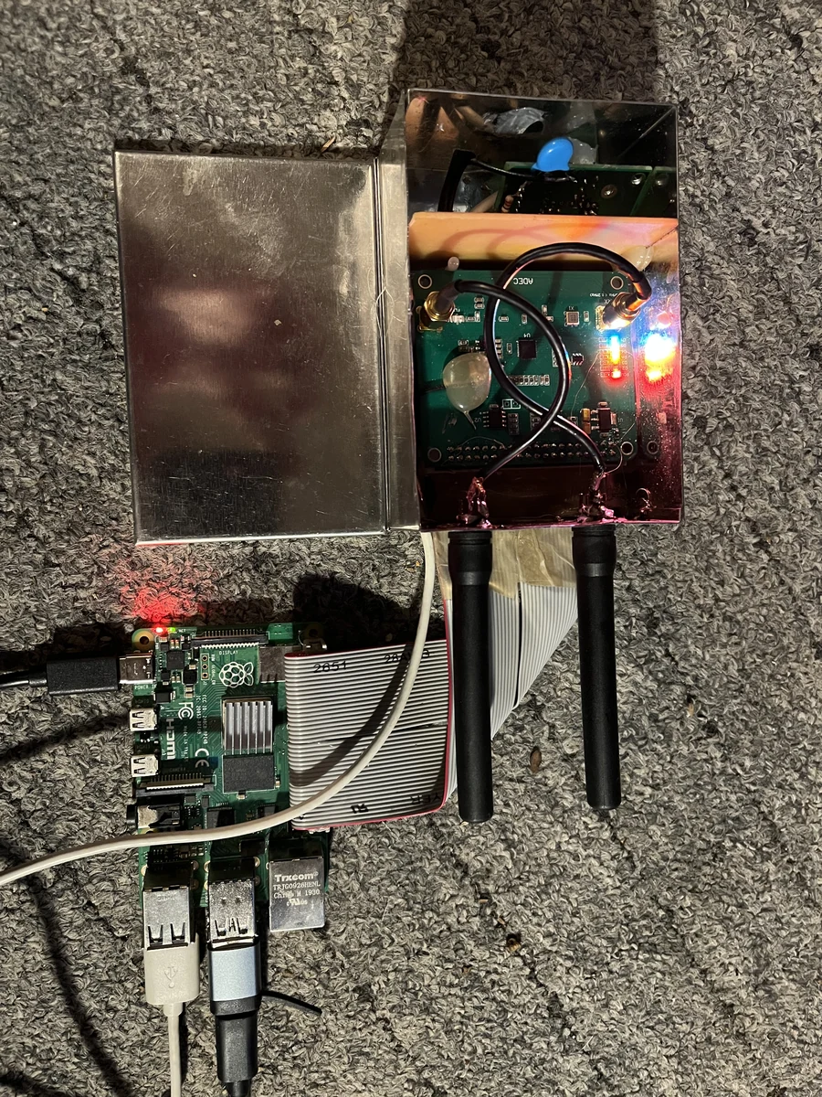
An external Si570 makes the SXceiver reference clock adjustable from the Pi. Combined with running I²S sample counters and chrony’s time reference, this forms a software frequency-control loop: the cell observes its mean clock deviation and corrects it during operation.
The first build replaced a failed TCXO. Automatic correction now runs at my station, making the modification interesting for longer-term operation of a shared TMO cell. This article documents the hardware, first comparison measurements and limits of the calculation.
This page covers the external oscillator, level adaptation and startup sequence. See setting up the TMO cell with Raspberry Pi, SXceiver and BlueStation for the complete station setup and current interface screenshots.
- Software frequency control
- Results and frequency comparison
- Starting point
- The SoftRock Si570
- Level adaptation and clock injection
- Clock first, then the cell
Software frequency control in operation
Si570 registers show the programmed value, not temperature-dependent deviation. Software therefore counts I²S samples delivered by the SX1255 and compares their progression with chrony’s corrected timebase. At the sample rate used here, 600,000 samples/s, each sample represents 64 cycles of the 38.4 MHz reference.
Chrony synchronises the Pi clock against external time servers. Evaluation accounts for ongoing clock correction and creates separate measurement windows for updated time models. The Pi’s oscillators remain part of that time measurement; the internet does not deliver a direct 38.4 MHz reference signal.
This is a frequency-locked loop (FLL). Corrections start when the quality indicator is at most 0.5 ppm, with at least three independent time-reference updates spanning at least five minutes. Uncertain warm-up values are excluded from current control. A new evaluation begins after each correction. The current release adapts its threshold to calculation quality and can correct below 0.5 ppm, with a lower limit of 0.05 ppm or the oscillator’s resolution.
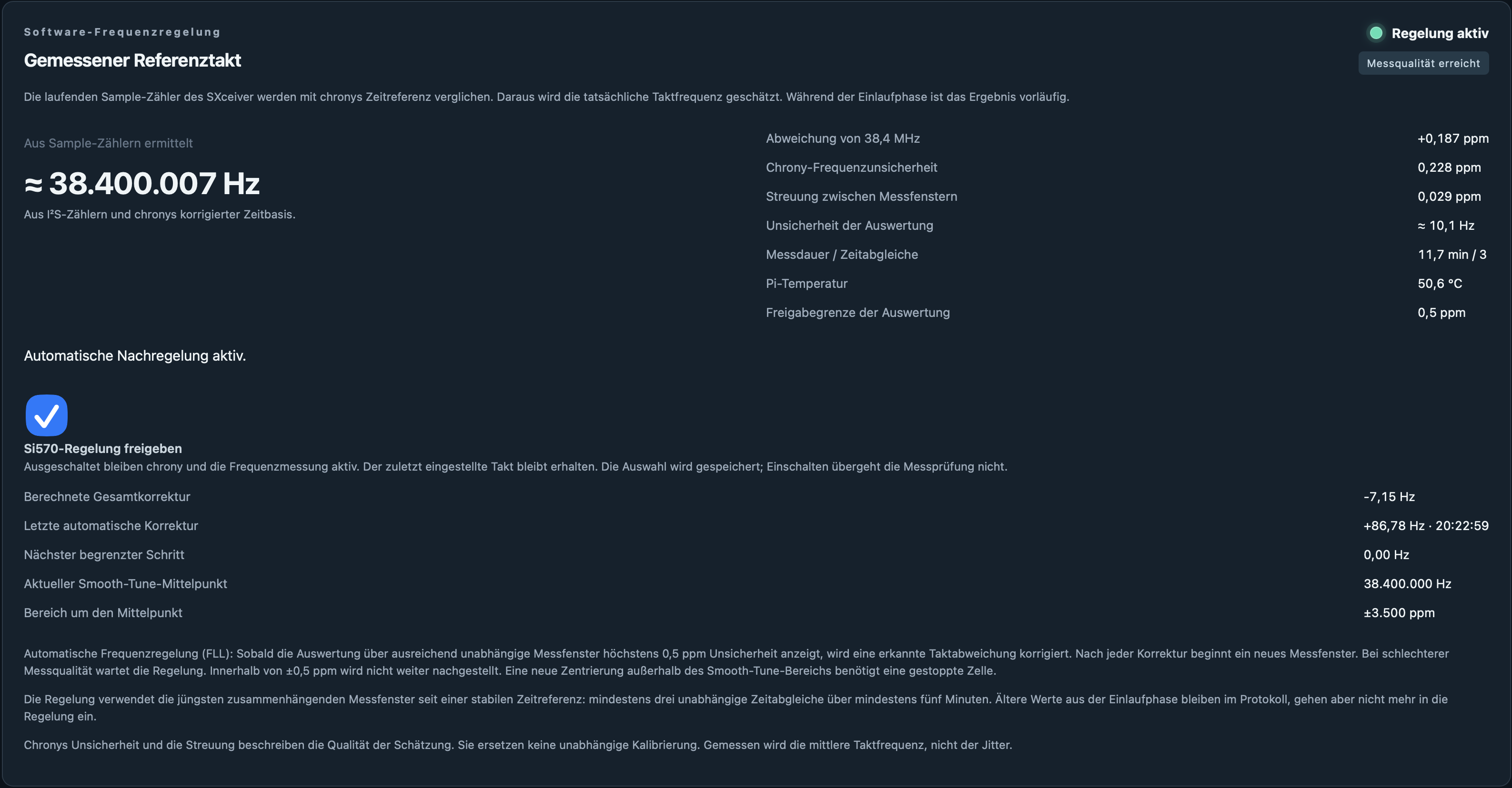
The USB controller applies the calculated correction to the Si570 over I²C. Software then checks the registers and continuity of both I²S streams. Changes stay inside the verified smooth-tuning range. Recentring beyond that range is not forced while the cell is running.
Control can be disabled independently of chrony. Time synchronisation and frequency estimation continue, and the last clock setting is retained. Invalid measurements or a detected hardware discrepancy prevent further automatic corrections.
Results and frequency comparison
Latest comparison: about +29 Hz · 16 November 2026, 23:33 CET
In the repeat comparison with a commercial transmitter, my operating cell on 438.275 MHz was only about +29 Hz, or +0.066 ppm, above the reference derived from that signal. The previous comparison with the same transmitter had shown about +94 Hz. In this recording, the cell was therefore substantially closer to the comparison reference.
| Comparison, 16 November 2026 | Relative residual offset of my cell | Equivalent |
|---|---|---|
| Previous comparison with the same commercial transmitter | about +94 Hz | +0.214 ppm |
| Repeat measurement at 23:33 CET | about +29 Hz | +0.066 ppm |
Scaled to the 38.4 MHz reference clock, this corresponds to a relative offset of about +2.54 Hz. This value comes from comparing the received RF signals; it is not a direct measurement at the Si570 output.
The recording sequence was: commercial transmitter, my cell, then commercial transmitter again. The same HackRF was retuned between frequencies, while the receive antenna and enabled antenna power remained unchanged. My cell operated throughout. The two measurements of the commercial transmitter differed by about 0.3 Hz. Each of the three recordings provided ten usable measurement windows with no detected clipping.
For the comparison, the receiver offset inferred from the commercial transmitter was interpolated in time and scaled by the ratio of the two RF frequencies. This calculation assumes the transmitter's nominal frequency. Its absolute accuracy and frequency-dependent HackRF errors have not been independently calibrated; different receive gains were also used. The +29 Hz is therefore a relative comparison result. The small 0.3 Hz change describes this short comparison, not its absolute measurement uncertainty. It establishes neither long-term performance nor oscillator jitter.
My cell in OnAir
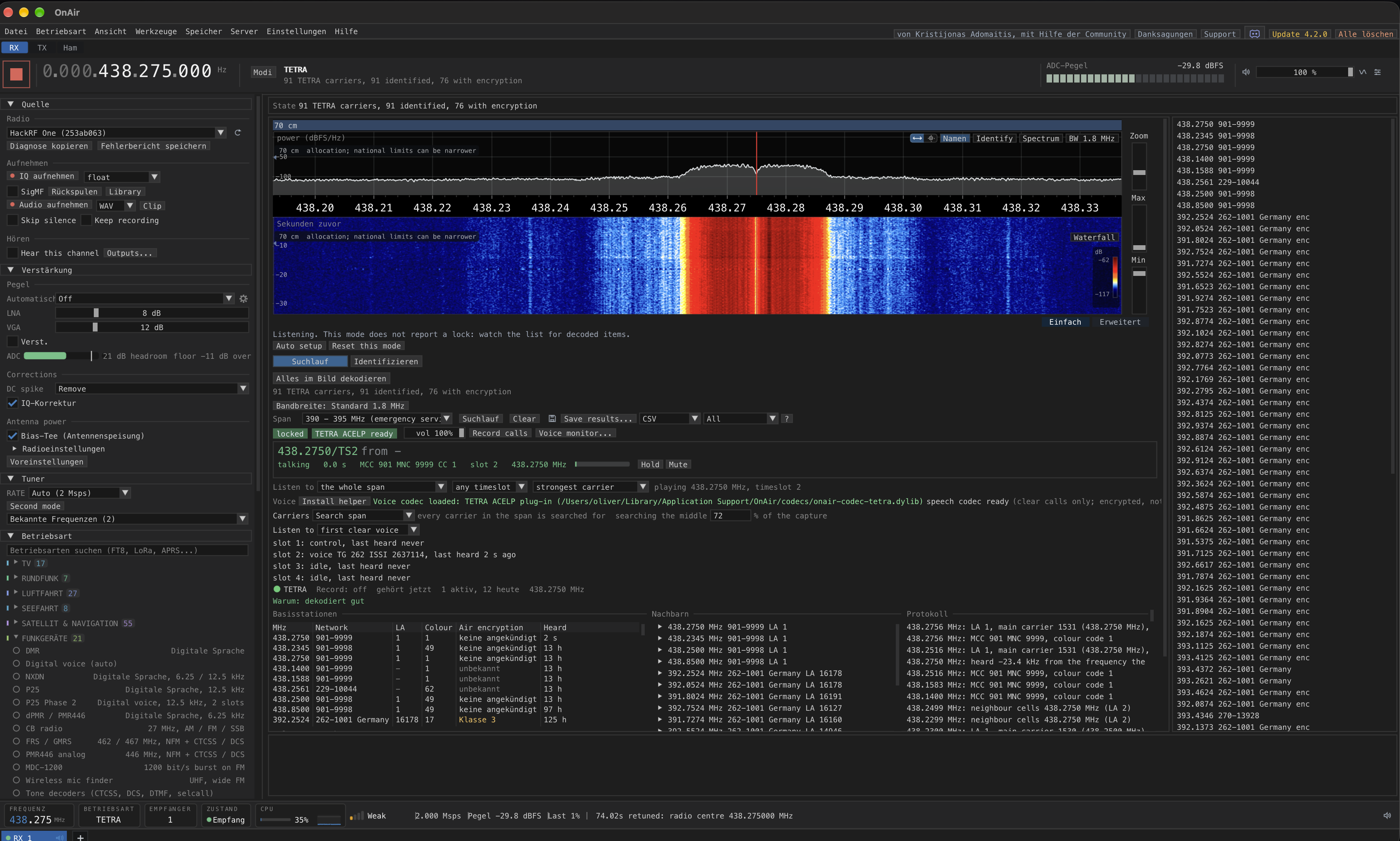
First measurement series after automatic correction
After the first automatic correction, my cell was compared with a commercial transmitter through the same HackRF. In this earlier series, tuning and receive antenna were unchanged; my transmitter was briefly stopped to record the commercial transmitter.
| Recording, 16 November 2026 | Relative offset of my cell | Equivalent |
|---|---|---|
| Before stopping the transmitter | about +72 Hz | +0.164 ppm |
| After restarting | about +95 Hz | +0.216 ppm |
| Last recording in this series | about +105 Hz | +0.240 ppm |
The measured difference between the two centre frequencies was compared with their known nominal spacing. Recordings were sequential. The commercial transmitter was not independently calibrated. These results support a plausible adjustment during the period examined; they establish neither guaranteed absolute accuracy nor long-term performance.
Small scatter values in the panel are not jitter measurements either. Chrony’s frequency uncertainty and scatter between windows describe calculation quality. Common errors and changing network delays can remain. Longer operation may improve the calculation, but uncertainty need not decrease continually.
For an open cell, an observable and adjustable reference is useful. Antennas, power, modulation and voice-path quality still require separate attention. Frequency control has been available since web interface 0.5.6 as an optional Pro feature, requiring a suitable external USB Si570 and the level adaptation described here.
Starting point: a failed TCXO
The cell initially worked, then began dropping out. Sometimes it started; sometimes it did not. I first suspected software: more interface features had just been added, so the timing fitted perfectly.
Troubleshooting covered power, connectors and drivers before reaching the reference clock. The SX1255 still responded, but the clock failed. The culprit was the board’s 38.4 MHz TCXO, which stopped working after about three hours.
A replacement was ordered, but I did not want to leave everything idle. An old, unused SoftRock RX Ensemble II in the office had a Si570.
The Si570 from the SoftRock
The receiver is by KB9YIG. I separated the section containing the Si570, USB controller and power supply and reused it as a standalone clock. The Si570 is controlled via USB: the ATtiny accepts USB commands and applies them over I²C to the oscillator.
The Pi can therefore set 38.4 MHz. USB powers the remaining assembly; its regulator supplies the Si570 with 3.3 V. The SoftRock oscillator documentation shows the circuit and components.
This Si570 has a CMOS output, so it could not simply replace the old TCXO without reducing its level.
Level adaptation and clock injection
I use CLK+, pin 4. The SoftRock board already has C35, 100 nF, at that output. The signal is taken after C35, on the side originally feeding the transformer. The transformer is no longer used.
A 220 Ω series resistor follows, with 100 Ω from the divider node to ground. From that node, a further 1 nF capacitor connects to the SX1255 reference input. The old TCXO output is disconnected.
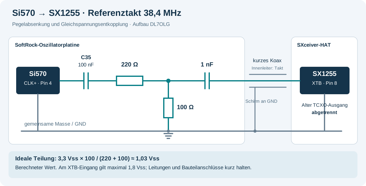
Ideally, the divider reduces 3.3 V peak-to-peak to about 1.03 V peak-to-peak. That is the calculated divider value; actual input level is decisive. The SX1255 datasheet specifies a maximum external clock of 1.8 V peak-to-peak at XTB, pin 8. This refers to clock signal amplitude, not the IC’s supply voltage.
Why another capacitor when C35 is already there?
C35 is before the divider. The 100 Ω resistor ties its output to ground at DC. The extra 1 nF capacitor is after the divider and isolates that ground connection from the SX1255 clock input’s operating point. The two capacitors serve different positions and purposes.
The blue capacitor in my build happens to be rated for 6 kV because it was in the parts box. This circuit does not need a 6 kV part; a small suitable ceramic capacitor is much easier to fit.
Spacing and a short piece of coax
The first assembly sat directly above the SXceiver and was sensitive enough that touching the USB cable could change operation.
The SXceiver TMO transceiver and Si570 board now share a metal enclosure, with some spacing between them. A short piece of thin Wi-Fi coax carries the clock: centre conductor for the signal, shield for common ground. Resistors and capacitors remain on the oscillator board, with connections kept short.
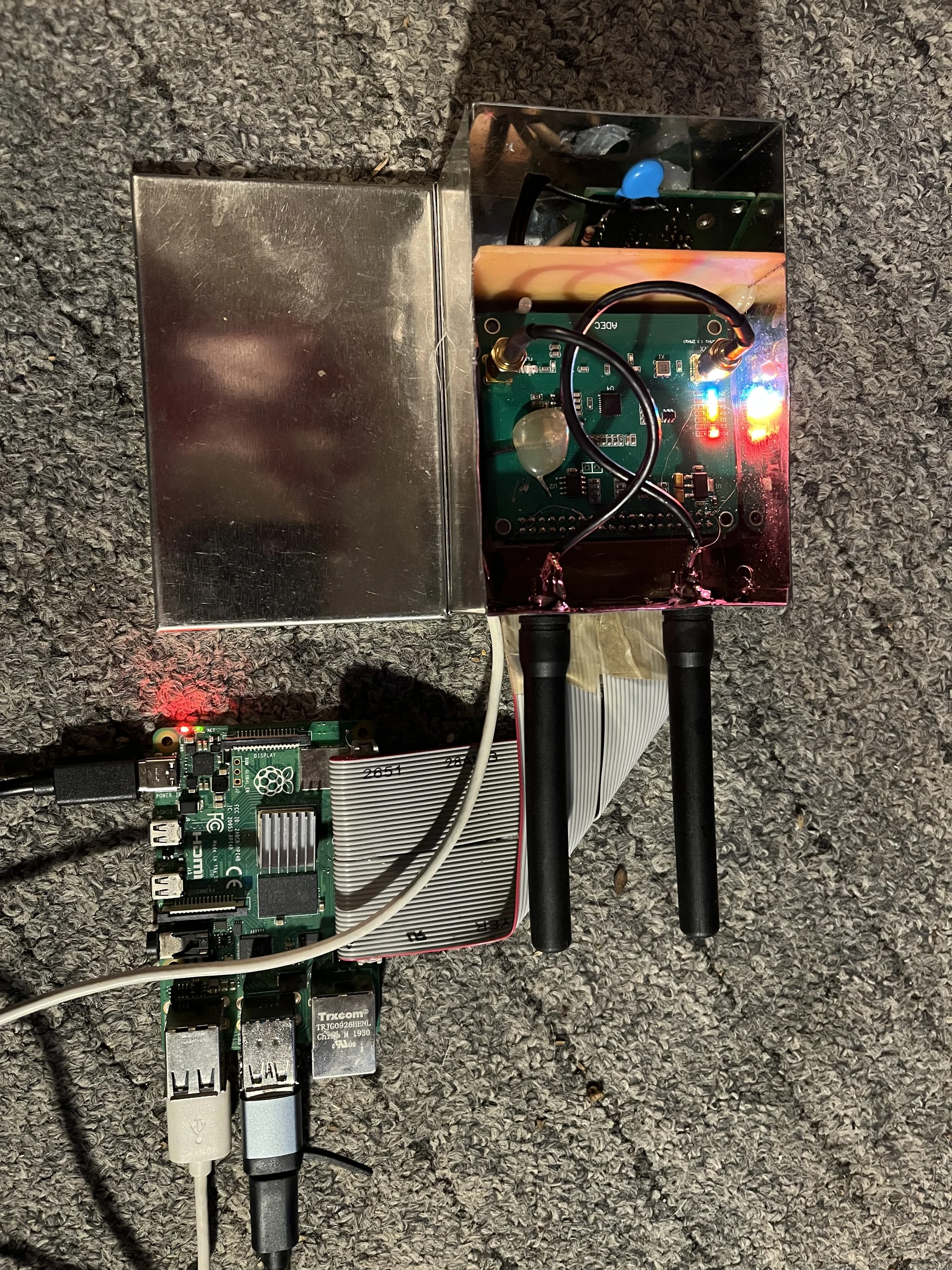
Touching the USB cable no longer affects operation here. The cell also runs again with a 30 dB TX mixer setting. This is a gain setting, not a measurement of transmitted watts.
Clock first, then the cell
Startup order matters with an external oscillator. The Pi must not start the radio service while the Si570 is still at its previous frequency.
A startup helper first sets the saved target, then reads back the registers. Only a successful check allows BlueStation to start. This happens before every transmitter start, including after a Pi reboot.
Hardware & Clock in the web interface shows reference-clock status, the two SX1255 PLLs, the frequency calculated from Si570 registers and USB/I²C connection status. Fine adjustment is possible with the cell stopped.
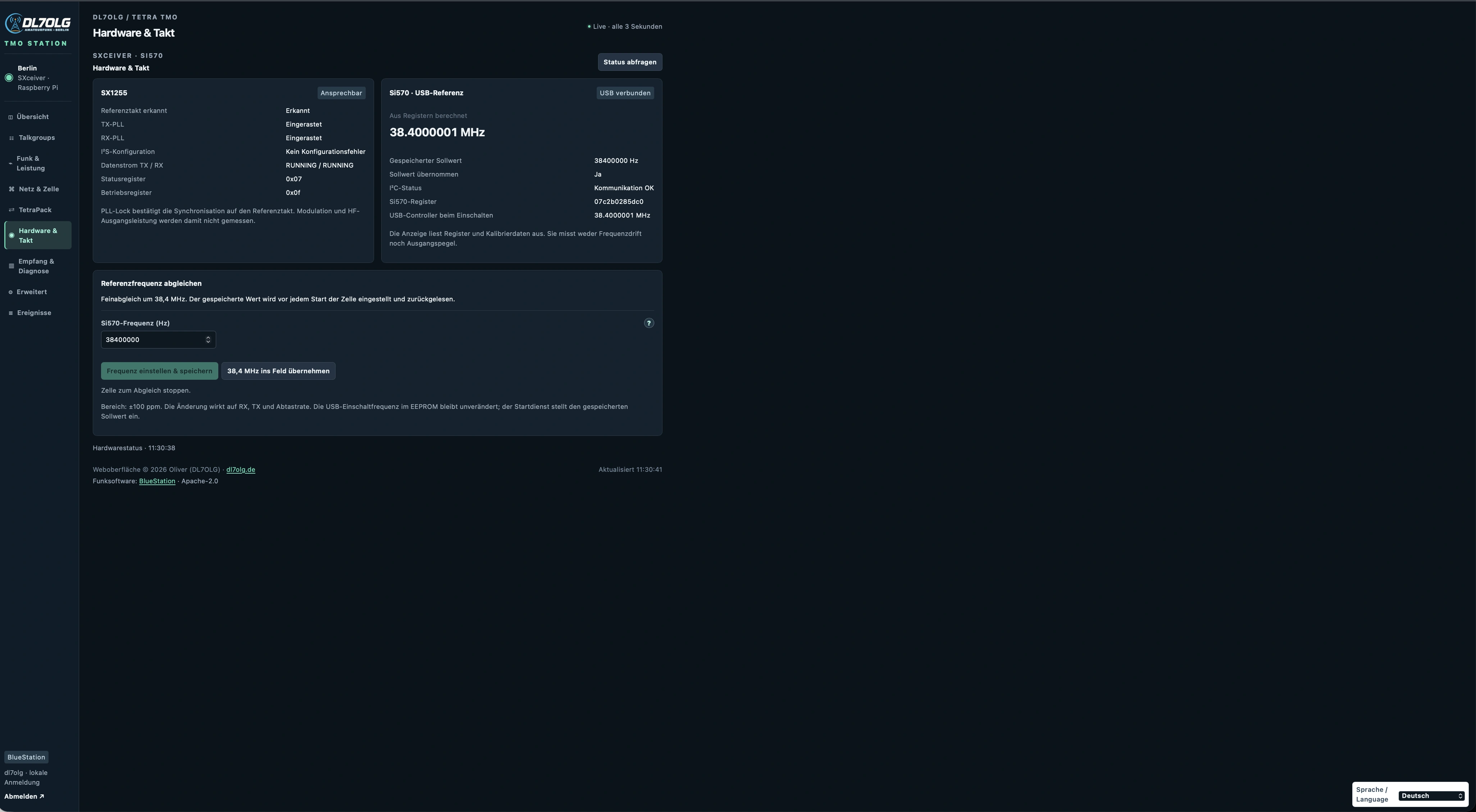
SX1255 status, Si570 register readback and fine adjustment at my station. Register readback describes the programmed state. The additional calculated frequency is shown above.
Si570 control and the startup helper are specific to this modification. A normal setup using the HAT’s oscillator does not need them.
The register display is a readback: a locked PLL confirms synchronisation to the reference clock. I also used the HackRF to inspect modulation and actual frequency at the antenna output.
The next step is a complete USB clock board with oscillator, controller, supplies and level adaptation. The Si598/Si570 board, dedicated firmware and wired schematic now have their own homebrew project. Electrical testing follows fabrication.
Documentation and related articles
- chronyc: synchronisation, frequency and skew
- PE0FKO: USB Si570 firmware and smooth tuning
- SoftRock RX Ensemble II: USB control and Si570
- Semtech SX1255 datasheet
- SXceiver and SoapySX — Tatu Peltola
- Set up a Raspberry Pi, SXceiver and BlueStation TMO cell
- Current TMO interface screenshots
Finer corrections
Pro 0.5.7 uses a threshold adapted to measurement quality. Deviations below 0.5 ppm can be corrected when they exceed current measurement uncertainty. The lower limit is 0.05 ppm or clock resolution. Several stable windows and a quality indicator no higher than 0.5 ppm remain prerequisites. Hardware & Clock displays the active threshold. The earlier screenshot records the state before this refinement on 16 November.
Later that evening
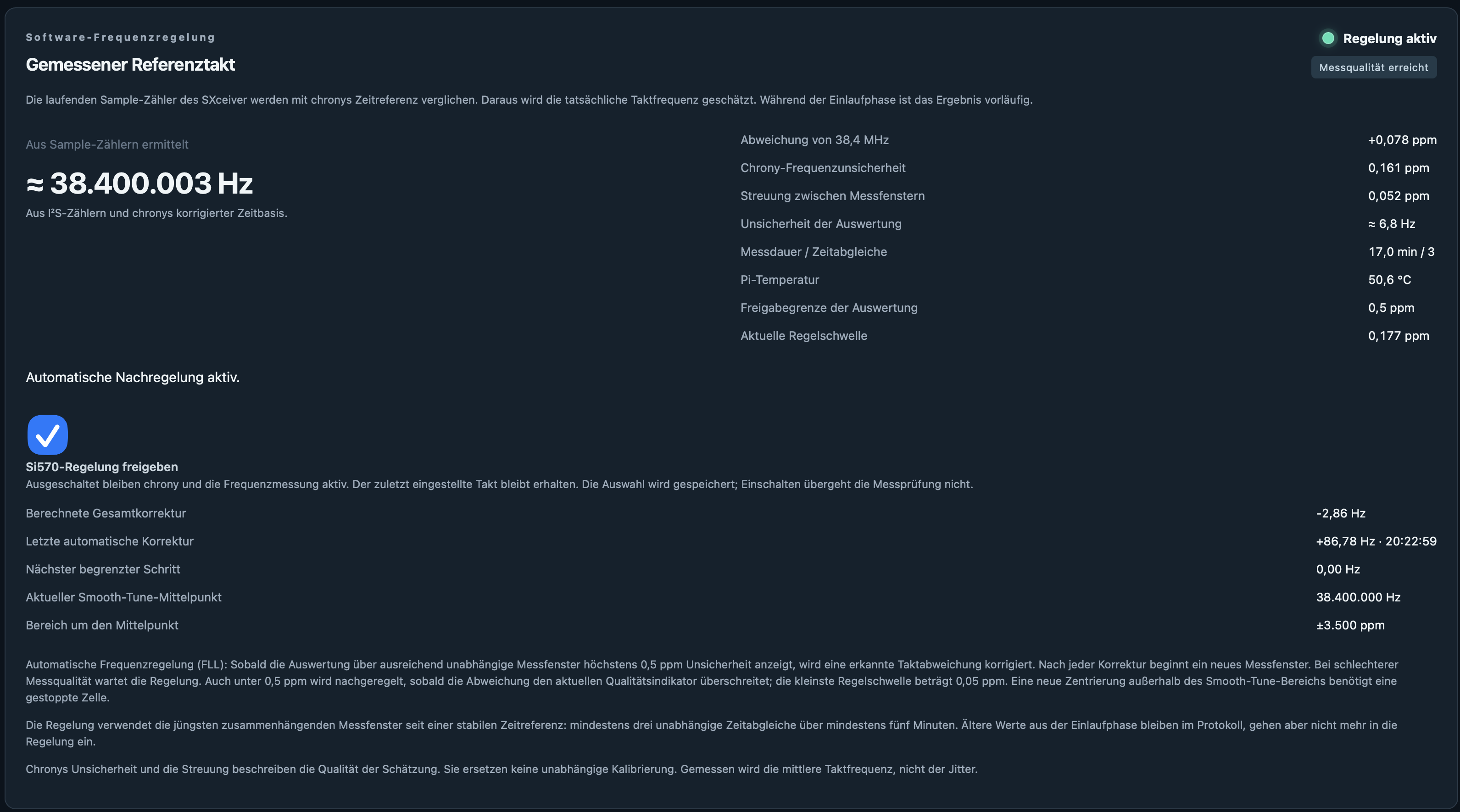
16 November 2026, 22:05: calculated reference clock ≈ 38,400,003 Hz, deviation +0.078 ppm. Chrony frequency uncertainty 0.161 ppm, scatter between windows 0.052 ppm and evaluation uncertainty ≈ 6.8 Hz. Active control uses a 0.177 ppm threshold here; the displayed deviation is below it, so no further adjustment is planned. These values describe the ongoing calculation and its quality, not independent calibration.