
An MTP850s has joined my Motorola collection, so this time the subject is TETRA. Here is how I configure it for amateur-radio TMO operation and which CPS settings are needed. Later sections cover GPS, forwarding to APRS and the orange emergency button.
DL7OLG · Updated 5 November 2026 · My radio: MTP850s H60PCN6TZ7AN, codeplug 7492, firmware R13.000.8661, CPS Plus 07.90.00.77. Menu names and settings refer to this combination. Adapt frequencies and network data to the cell you intend to use.
1. Cell details and network authorisation
Before programming, obtain the cell’s output and input frequencies, MCC/MNC, duplex index and talkgroups. Cell output is the frequency received by the handheld. This guide uses the following example:
| Parameter | Example |
|---|---|
| MTP850s receive / cell output | 438.250 MHz |
| MTP850s transmit / cell input | 430.650 MHz |
| Duplex spacing | 7.600 MHz; handheld transmits below cell output |
| MCC / MNC | 901 / 9998 |
| Duplex index in the example | 1; confirm separately for the target network |
Get these values from the operator or their technical documentation. Do not simply copy every screenshot.
Having a DMR ID does not automatically register you on a TETRA network. For cells in the tmo.services network, the SysOp may need to add or authorise you. Ask first, providing your callsign, RadioID/DMR ID and radio model/manufacturer. Procedures vary; not every network offers a self-registration website.
Activation may take time. Restart the radio afterwards. If registration still fails, the SysOp can examine the failed attempt.
2. Data cable and programming mode
You need a charged battery, a suitable USB data cable and CPS compatible with your radio and codeplug version. The LAB functions used below must also be available.
An old phone cable may be useful: I use a USB data cable from an old Motorola V-series phone, such as the V60/V400. The pinout is identical, and used cables are inexpensive on eBay. Those phones’ chargers are compatible too.
V60 connector type: MTP850s pinout
The drawing shows the 17-pin MTP850s CE connector and the contact face of the matching V60-type plug. Use the three broad contacts 1–3 for orientation. Looking at the cable plug mirrors the order at the radio connector. Both views show contacts, not solder terminals.
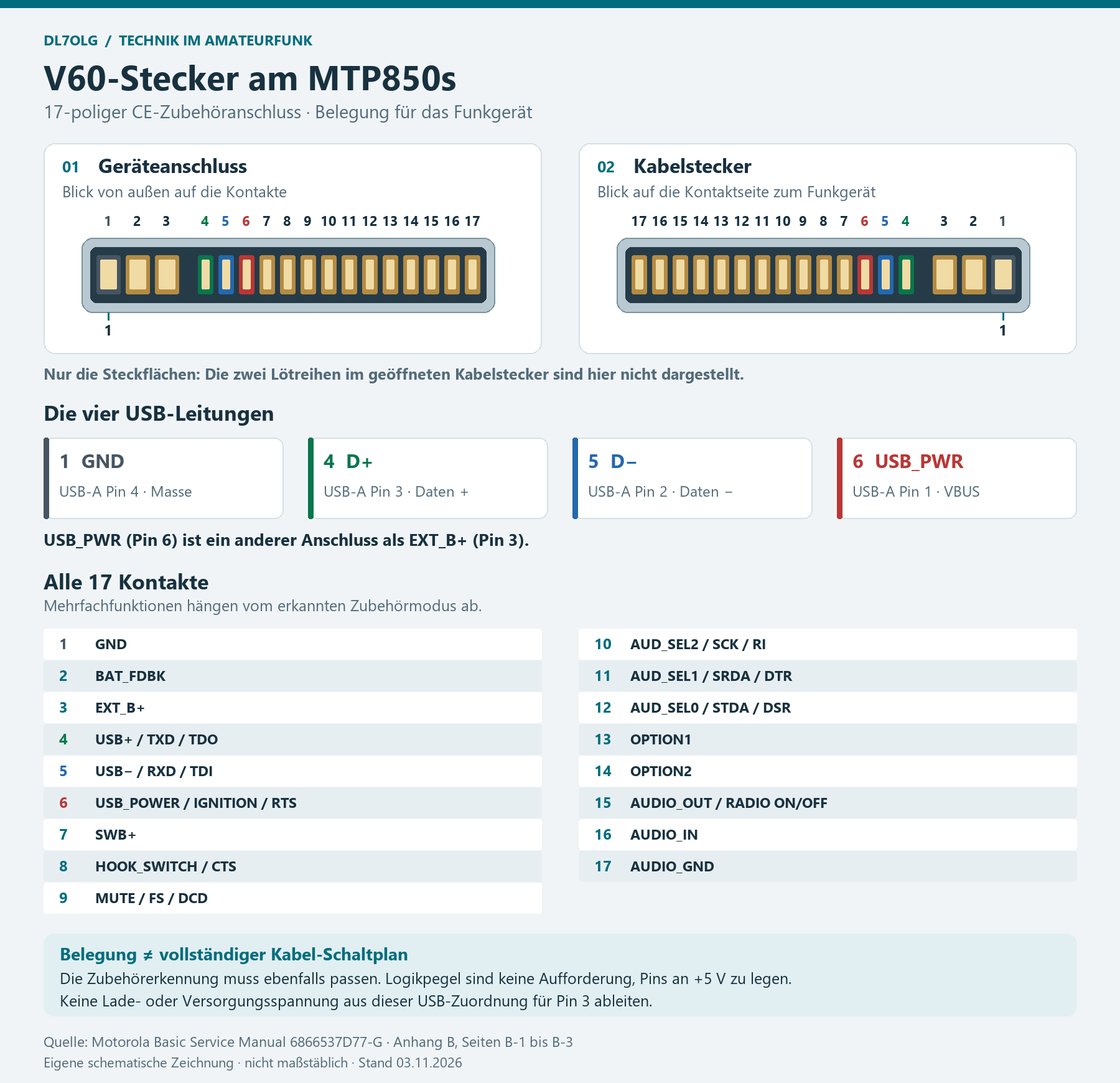
If you open the plug, the solder terminals are arranged in two rows. Do not simply mirror the drawing and solder from that. Trace each terminal to its contact or test continuity with the cable disconnected.
USB requires 1 = GND, 4 = D+, 5 = D−, 6 = USB_PWR. Do not confuse USB_PWR with EXT_B+ on pin 3; they are separate. The charging voltage for pin 3 cannot be inferred from this USB pinout.
| Pin | Signal / alternate function | Purpose |
|---|---|---|
| 1 | GND | Ground |
| 2 | BAT_FDBK | Battery feedback |
| 3 | EXT_B+ | External power |
| 4 | USB+ / TXD / TDO | USB D+ |
| 5 | USB− / RXD / TDI | USB D− |
| 6 | USB_POWER / IGNITION / RTS | USB supply / detection |
| 7 | SWB+ | Switched battery voltage |
| 8 | HOOK_SWITCH / CTS | Accessory control |
| 9 | MUTE / FS / DCD | Accessory control |
| 10 | AUD_SEL2 / SCK / RI | Accessory control |
| 11 | AUD_SEL1 / SRDA / DTR | Accessory control |
| 12 | AUD_SEL0 / STDA / DSR | Accessory control |
| 13 | OPTION1 | Accessory mode |
| 14 | OPTION2 | Accessory mode |
| 15 | AUDIO_OUT / RADIO ON/OFF | Audio / power control |
| 16 | AUDIO_IN | Audio input |
| 17 | AUDIO_GND | Audio ground |
This pin list applies to the MTP850s; it is not a universal Motorola phone-cable construction guide. A homebuilt cable also needs accessory detection. The service manual specifies “USB Accessory/Computer” as OPTION1 = High, OPTION2 = High, USB_PWR > 4.0 V, and AUDIO_IN = High. “High” means a logic state, not permission to connect +5 V directly to every pin.
Connect to CPS
- Start CPS and connect the switched-off radio using the data cable.
- Hold 1 + 9 + Power together for about three seconds.
- Wait for CPS to display the radio icon.
- Read your own codeplug using File → Read Radio.
- Save the unchanged file with a clear name using File → Save As.
“USB connected” on a normally started radio is insufficient: reading requires programming mode. If CPS does not detect it, check cable, driver and programming mode first. You may restart CPS once no read/write operation is running.
If a CPE file cannot be opened because of its codeplug version, check that model, codeplug version, CPS and release package match. A similar firmware filename does not solve that. Renaming or altering another radio’s identity does not make its file compatible.
3. Back up first
Before LAB changes, save the complete codeplug read from your own radio. In addition to CPE, make a full flash dump:
- Open Lab → Flash Report.
- Choose a new Flash Image Filename.
- Set Report Type → Entire Flash.
- Select your own radio under Selected, then choose Start Operation.
- Wait for successful completion and keep another copy elsewhere.
CPE is needed for further CPS work. Exported user-data XML contains only certain tables, such as contacts and groups. The flash dump is an additional service backup. Keep them separately: XML alone is not a complete radio backup.
4. Enter LAB mode
- Keep the backed-up codeplug open.
- Click L on the left for LAB view.
- Click D for decimal display.
- Navigate under
cp_all_tto the blocks below.
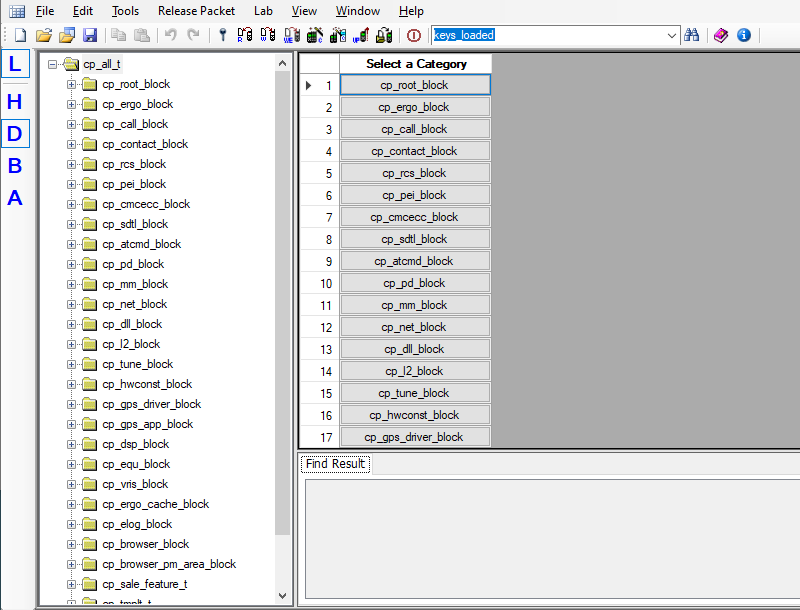
LAB frequencies are in hertz: 440000000 is 440 MHz; 7600000 is 7.6 MHz. Normal Frequency List2 uses MHz. Expand opens the associated subtable. Follow the frequency steps in order, leaving your radio’s serial number, TEI, model identity and calibration unchanged.
5. Set frequency ranges
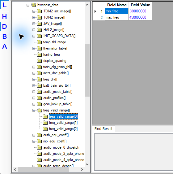
Open cp_hwconst_block → hwconst_data → freq_valid_range[] → freq_valid_range[0]. Its min_freq and max_freq must cover both intended RX and TX frequencies.
Next open cp_net_block → net_data → TMO_range_table[]. My MTP850s has 16 entries, [0] to [15]. Check all of them:
- Open
[0]and inspectmin_rx_freqandmax_rx_freq. - Set the required TMO receive range.
- Repeat for every entry through [15], including [9]–[15].
- Check all subtables again before writing.
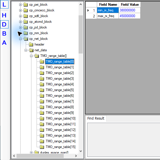
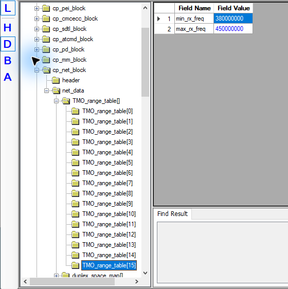
For 430–440 MHz, enter 430000000 and 440000000. My screenshots show a broader software range, 380–450 MHz, which is unnecessary for the 438.250/430.650 MHz example. Being able to enter a wider range does not measure how well the radio operates outside its original band.
For DMO, also check cp_net_block → net_data → DMO_range, with separate min_rx_freq and max_rx_freq limits.
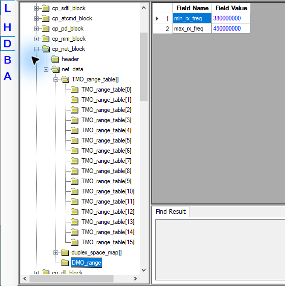
Changing only the first TMO entry or adding a search frequency is insufficient; the ranges across the tables must agree.
6. Set duplex index and spacing
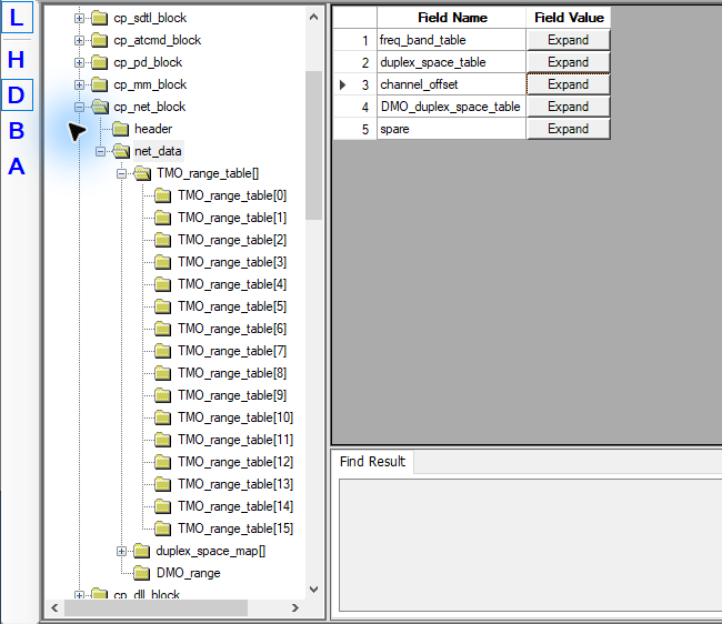
- Select
cp_net_block → net_data. - Click Expand beside
duplex_space_table. - Locate the field index used by the cell. The number at the far left is only a row number.
- Enter spacing in hertz at the confirmed index. If the network uses index 1 for 7.6 MHz, enter
7600000there.
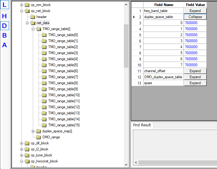
The example is 438.250 MHz receive − 7.600 MHz = 430.650 MHz transmit. Enter positive spacing; cell channel information determines whether the radio transmits above or below cell output.
Different cells may use different indices. You can enter 7.6 MHz correctly but in the wrong entry. Confirm the index with the operator.
Some codeplugs also contain duplex_space_map[] → spacing and DMO_duplex_space_table. Check the full path: this step concerns duplex_space_table. Do not set all similar tables or indices to the same value.
7. Enter your ID and network identity
- Use L to return to normal CPS view.
- Open Subscriber Unit Parameters.
- Enter your own RadioID/DMR ID authorised for the network under Radio ISSI.
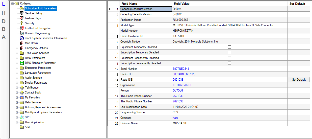
I now use 2636912 for TETRA. The screenshot still shows 2621039, my DMR ID. Use your own authorised TETRA ID. Leading zeroes do not change its numeric value: 02636912 and 2636912 are identical. Use Radio ISSI; This Radio Phone Number and This Radio Private Number do not replace it.
- Open Mobility and System Parameters → Address Extension.
- Enter the target network, for example Country Code 901 / Network Code 9998.
- Choose an unambiguous alias, such as AFU TMO 9998.
- To use 901/9999 as well, add a separate entry and clarify access with its operator.
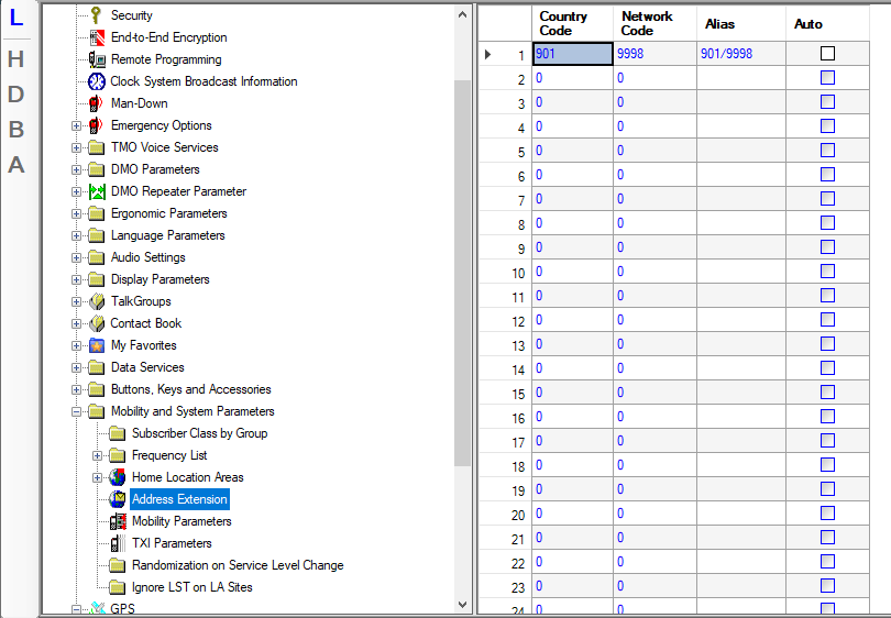
9998 and 9999 are different network identities. An alias is just a displayed name. Two entries do not register the radio on both networks simultaneously. Select the intended network for the first test and check the home-network identity on the radio; the alias alone does not prove it is correct.
The screenshot shows 901/9998. Add another row for 901/9999 if required. Ask the operator which network the cell currently belongs to and which groups or BrandMeister links are available; identity alone does not establish those details.
8. Enter search frequencies
- Open Mobility and System Parameters → Frequency List → Frequency List2.
- Enter actual cell output — 438.250 MHz in this example.
- Add other cell outputs you actually need.
- Add further search ranges in Frequency List3/List4 if needed.
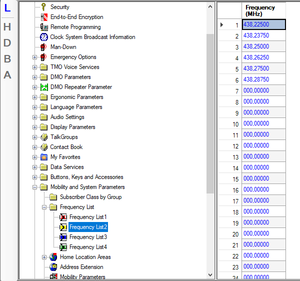
Frequency List2 supplies the initial targeted search. CPS help describes Frequency List1 as dynamic. It also distinguishes home and foreign networks: these fields apply in the home network, while network-wide settings are used in a foreign one. Check network selection if a listed cell is not found.
Additional search ranges
Frequency List3 and List4 use a start frequency and frequency count on a 25 kHz raster. Six frequencies from 438.225 MHz give 438.225, 438.250, 438.275, 438.300, 438.325 and 438.350 MHz. Check both entries and include only relevant areas.
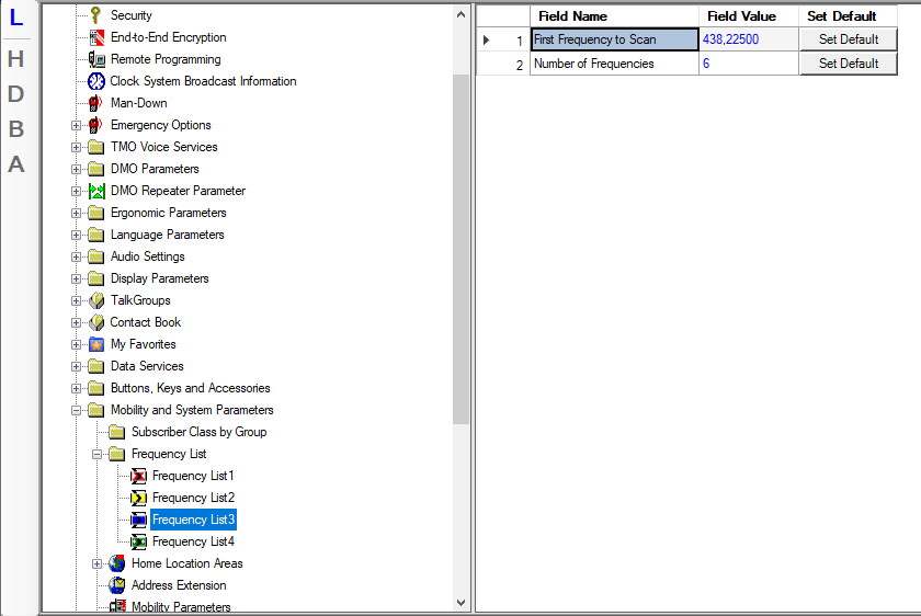
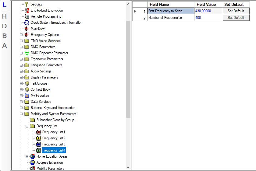
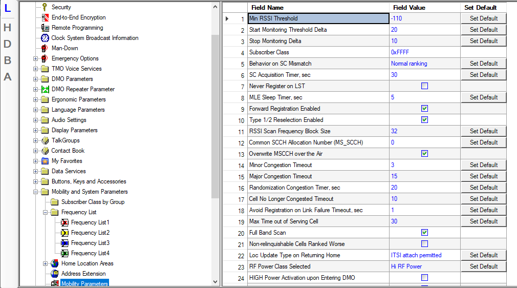
Enable TMO on the radio. Disable TXI transmit inhibit for registration, or the radio cannot reply. Initially retain known appropriate minimum-RSSI and monitoring-delta settings. Lowering the RSSI threshold does not improve receiver sensitivity.
9. Encryption and network registration
Under Security, match authentication and air-interface encryption to the operator’s settings for this unencrypted amateur cell. Air-interface encryption, end-to-end encryption and advertised radio capabilities are separate concepts.
A checked greyed-out box does not prove encrypted transmission. In my CPS, GCK Air If Encryption and OTAR and DMO SCK OTAR depend on other settings. They can be locked in normal view while the associated LAB values remain set.
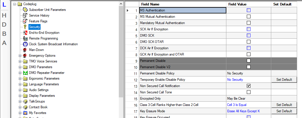
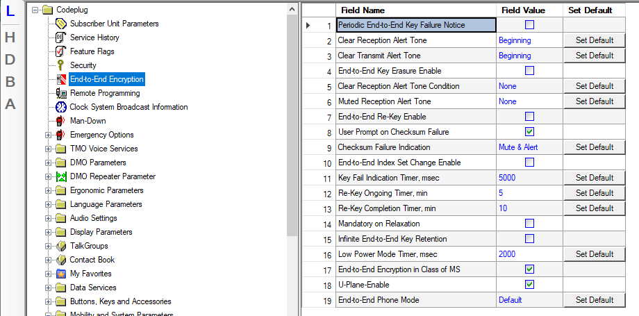
Do not alter LAB values speculatively. Use confirmed network settings for OTAR, key status and capabilities. A field’s presence does not establish whether transmission is encrypted or a key prevents registration.
This guide leaves undocumented status fields such as class3_keys_valid alone. A single value cannot reveal all keys in the radio. If the network does not know your subscriber identity, toggling encryption does not authorise you.
10. Create TMO folders and talkgroups
- Open TalkGroups → TMO → TMO Folders List.
- Create TETRA TMO, with status Programmed.
- Open TMO Talkgroup List.
- Enter network groups with Name, numeric ID and Status: Programmed.
- Assign the appropriate Default Folder.
- Verify membership under Talkgroups In Folder, or use the group’s Add to Folder context-menu command.
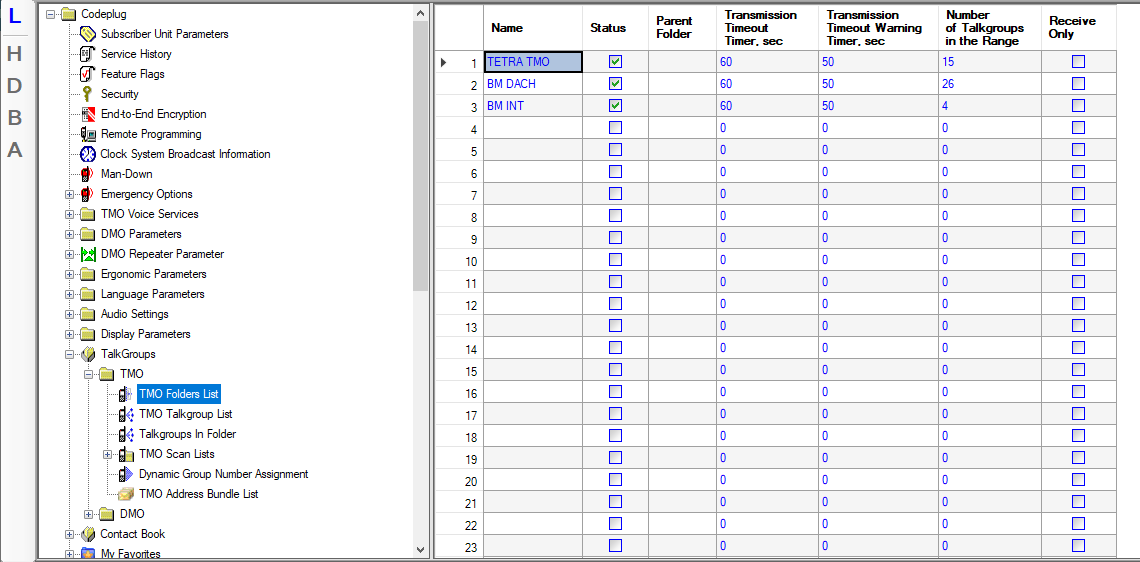
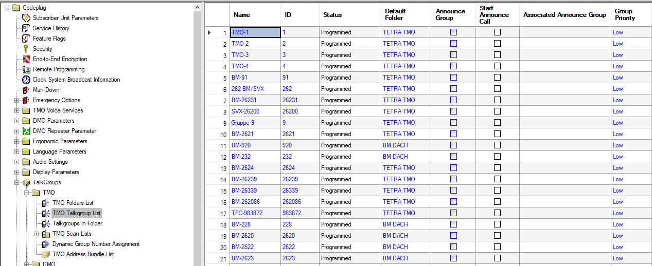
A TETRA group ID is GSSI; your individual subscriber number is ISSI. See tmo.services → Groups or ask the operator for IDs. Entering a BrandMeister group number alone does not create a BrandMeister connection.
Start with a few groups agreed with the operator. Confirm registration before testing group operation. A matching codeplug group does not replace subscriber authorisation.
If TMO Talkgroup List becomes extremely slow, stop repeatedly clicking. Export a saved state using File → Export → User Data, edit the XML in a suitable editor, then use File → Import → User Data. Start from your latest complete export; groups, folders and cross-references must agree. Check for missing and duplicate entries afterwards.
11. Add contacts
- Open tmo.services → Contact Lists.
- Select Motorola.
- Transfer the data into the matching Contact Book → Contact List CPS table structure.
- Spot-check callsign/name, Personal status and private subscriber number.
- Check existing contacts, groups and folders for completeness before writing.
The website provides Motorola and Sepura data. Use Motorola for the MTP850s. If columns do not match your CPS version, use your current user-data XML export as the template and map fields accordingly. Do not import a complete foreign XML over existing groups and folders.
Contacts let the radio display names for subscriber numbers. Your ISSI still needs network authorisation; contact import does not provide it.
12. Write and verify the codeplug
- Save the prepared file under a new name.
- For LAB changes, switch to LAB view and verify your target radio.
- With the tested CPS 07.90.00.77, use File → Write Radio and wait for completion.
- Read the radio again and check the changed values.
- Save the verified CPE as your new working copy.
Older amateur guides often say Write Entire Codeplug. In my CPS Plus 07.90.00.77, Write Radio and Write Entire Codeplug use the same LAB write path while in LAB view. This statement is specific to that version and mode. Read back to verify. Leaving LAB view does not itself require another write.
Keep power and USB connected during writing. Use the complete codeplug read from this exact radio; another radio’s complete image also carries its identity and calibration.
13. Register and try it
- Start the radio normally after programming.
- Select TMO and the intended network.
- Select folder TETRA TMO and an agreed group.
- Wait for successful network registration.
- Make an agreed short group test.
| Observation | Next check |
|---|---|
| No network found | Reception, target network, Frequency List2, global and all TMO frequency limits. |
| Cell found, registration fails | Radio ISSI, network identity and operator authorisation; have the SysOp examine the specific attempt. |
| Expected uplink absent | TXI, duplex index and actual TX frequency. Brief bursts can be missed in a spectrum display. |
| Registered, group does not work | GSSI, folder membership and network-side group availability/linking. |
| Change appears ineffective | Read the radio again and compare its actual state. |
Radio errors alone may be inconclusive. The SysOp can check whether registration reaches the network and is rejected. A correctly decoded control-channel response can also distinguish rejection from reception trouble. Provide ISSI, MCC/MNC, cell and attempt time.
14. Configure GPS
The MTP850s has GPS for displaying position and sending it through TETRA. More than GPS reception is needed: the radio must transmit a report and the network must forward it to APRS. First confirm valid coordinates on the radio itself.
Here are my LIP over SDS settings from my codeplug. Ask the operator whether the network supports that location service and which destination to use. My values are not universal. Back up your radio again first.
Open GPS Settings
In normal CPS view, open GPS → GPS Settings. These GPS/emergency settings need no additional LAB changes.
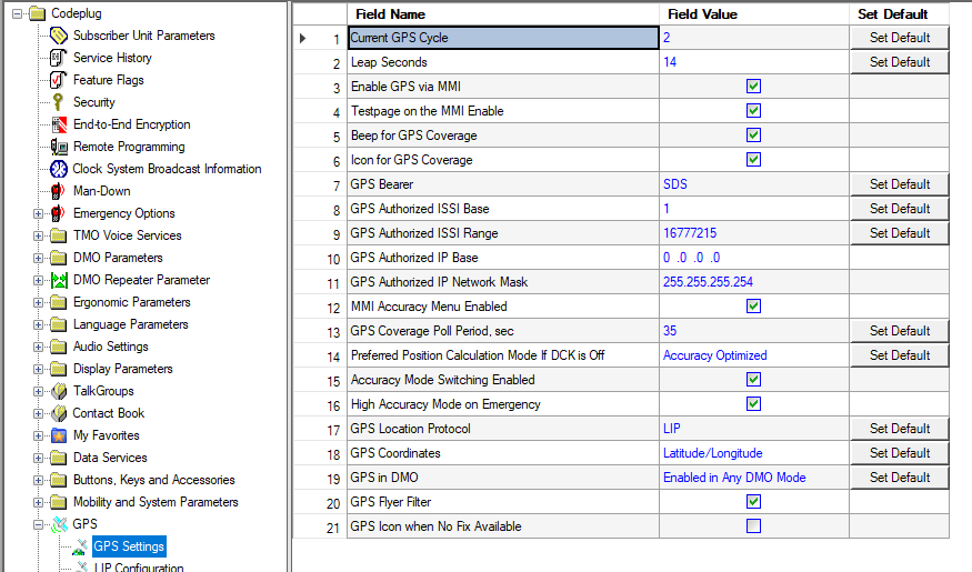
| Field | Example | Meaning |
|---|---|---|
| Current GPS Cycle | 2 | GPS week cycle for 7 April 2019–20 November 2038; cycle 2 applies in 2026. |
| Enable GPS via MMI | Enabled | Allows menu control; check GPS is on at the radio afterwards. |
| Testpage on the MMI Enable | Enabled | Enables the GPS test/information page. |
| Icon for GPS Coverage | Enabled | Displays GPS coverage. |
| GPS Icon when No Fix Available | Disabled here | Icon may disappear without a fix; absence alone does not prove GPS is off. |
| GPS Bearer | SDS | Carries location reports through TETRA short data service. |
| GPS Location Protocol | LIP | Location Information Protocol; requires network support. |
| GPS Coordinates | Latitude/Longitude | Geographic coordinates. |
| Preferred Position Calculation Mode If DCK is Off | Accuracy Optimized | Prefers accuracy over lower power use. |
For this November 2026 setup, Current GPS Cycle = 2 assigns the GPS week number to the correct period. It does not increase satellite-search frequency or receiver sensitivity and does not guarantee a fix. The screenshot’s Leap Seconds field holds an old saved value: it represents GPS-to-UTC correction, so do not copy it as a current recommendation.
I also enable Beep for GPS Coverage, MMI Accuracy Menu Enabled, Accuracy Mode Switching Enabled and High Accuracy Mode on Emergency. GPS Coverage Poll Period is 35 seconds; this is not the APRS reporting interval. GPS in DMO: Enabled Any DMO permits GPS in direct mode, but does not create an APRS connection without a suitable gateway.
“Authorized ISSI” is not the destination
GPS Authorized ISSI Base/Range define who may query the radio’s position. My screenshot shows 1 and 16777215, a very broad range. This is unnecessary for GPS reception and does not mean all senders must be allowed. Use the range specified for your operator’s query service.
GPS Authorized IP Base/Network Mask are not APRS destination fields either. This SDS profile’s report destination is under LIP Configuration → Destination ISSI.
15. Send GPS reports using LIP and SDS
Destination
Open GPS → LIP Configuration. My Destination ISSI is 9999; use it only if your location service uses that address. It is unrelated to MNC 9999 in network selection.
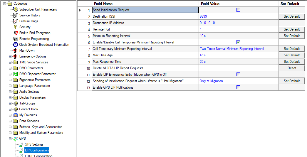
| Field | Example | Meaning |
|---|---|---|
| Send Initialization Request | Disabled | This profile requires no preceding server initialisation. When enabled, relevant transmission waits for a valid server response. |
| Destination ISSI | 9999 | Network-dependent recipient of LIP reports. |
| Minimum Reporting Interval | 10 s | Minimum spacing for applicable reports, not the periodic interval; some triggers have exceptions. |
| Enable/Disable Call Temporary Minimum Reporting Interval | Enabled | Uses a temporarily longer minimum interval during a call. |
| Call Temporary Minimum Reporting Interval | Two Times Normal Minimum Reporting Interval | Twice the normal minimum here. |
| Max Data Age / Max Response Time | 45 s / 20 s | Position-data age and response-time limits; some triggers have their own values. |
Do not enter aprs.fi’s internet address in Destination IP Address for this SDS setup. Leave Delete All OTA LIP Report Requests alone unless deliberately deleting previously received over-the-air reporting requests. It is not needed for this setup.
Periodic reports
Under GPS → LIP Triggers → Periodic, set Enabled to Enabled. My Max Reporting Interval is 2.5 min, or 150 seconds; Max Data Age is 45 seconds and Max Response Time 20 seconds.
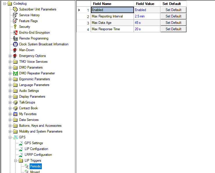
Keep these three times distinct: reporting interval determines spacing, data age limits how old a position may be, and response time limits the intended response delay. A longer interval may suit your network; follow the operator’s initial recommendation. The normal Periodic trigger applies outside emergency mode.
Reports after movement
Under GPS → LIP Triggers → Moved, I enable the trigger with Max Reporting Distance = 300 m, Distance Check Interval = 60, Max Data Age = 30 s and Max Response Time = 20 s. Adapt distance to your use.
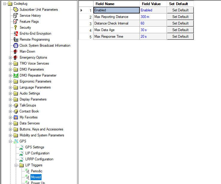
This adds movement-triggered reports to periodic ones. It should not continually generate extra packets when stationary. Other triggers, such as mode changes or restored GPS coverage, remain unchanged for this basic setup.
Position report on entering emergency mode
Under GPS → LIP Triggers → Emergency, I use Enabled, Max Data Age = 30 s and Max Response Time = 16 s.
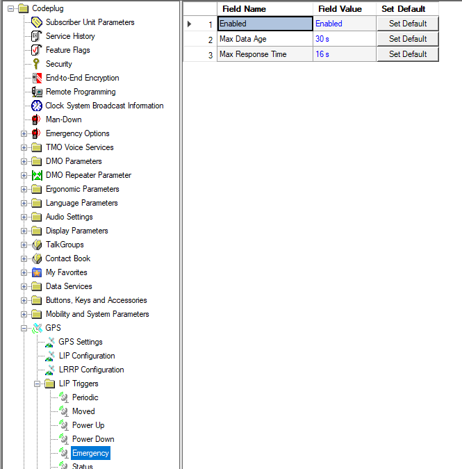
This controls only location reporting. Voice group and open-microphone duration are separate. Valid coordinates still require a fix. Enable LIP Emergency Entry Trigger when GPS is Off stays off in my LIP configuration; this profile does not require it.
16. Configure the orange emergency button for TMO
The orange button can trigger an alarm and voice call, with the LIP trigger adding a position report. Each has separate settings. In amateur radio, this button does not automatically call 112 or a public emergency control centre. It reaches the configured group or recipient in your network.
Enable alarm and voice call
In Emergency Options, I enable TMO Emergency Alarm and TMO Emergency Call. Silent Emergency = Disabled; this is not a silent emergency. TMO Emergency SDS Status stays off. LIP location reporting is separate.
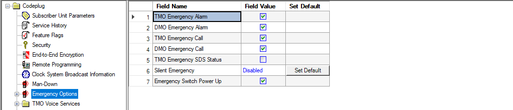
Emergency Switch Power Up is also enabled, allowing the button to turn a switched-off radio on in emergency mode. The screenshot shows DMO options too; they would require their own suitable DMO destination. This guide stays with TMO.
Button hold times
Under Emergency Options → MMI Options, Emergency Started Timer, msec = 500 and Emergency Cancel Timer, msec = 2000 mean 0.5 seconds to trigger and 2 seconds for the designated cancellation action. Choose a longer trigger hold if half a second risks accidental activation.
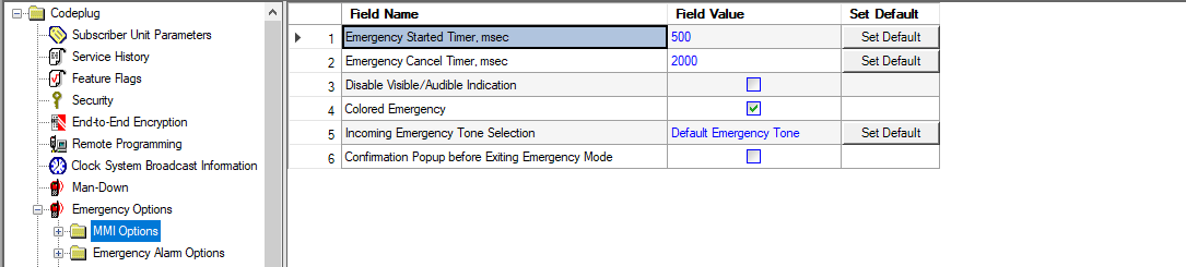
I enable Colored Emergency and disable Disable Visible/Audible Indication. These affect emergency display/signalling, not GPS fix.
Use the selected talkgroup
Under Emergency Options → Emergency Call Options → Emergency Call Destination – TMO, choose Emergency Address Type = Group. This reveals Emergency Group Type; I select Tactical.
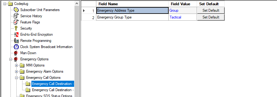
Tactical uses the currently selected and attached talkgroup; it is not another group ID. A fixed emergency group requires agreement with the operator and a non-tactical destination. Entering an arbitrary GSSI does not turn it into a general emergency service.
Send the alarm to the same destination
Under Emergency Options → Emergency Alarm Options → Emergency Alarm Destination – TMO, set Destination = Same as Emergency Call.
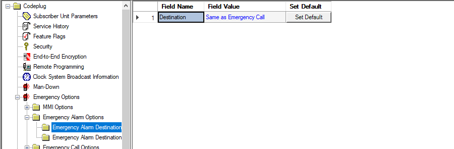
Position reports retain their own Destination ISSI under LIP Configuration. A voice call reaching the correct group does not establish that APRS received the position.
Optional: open the microphone automatically
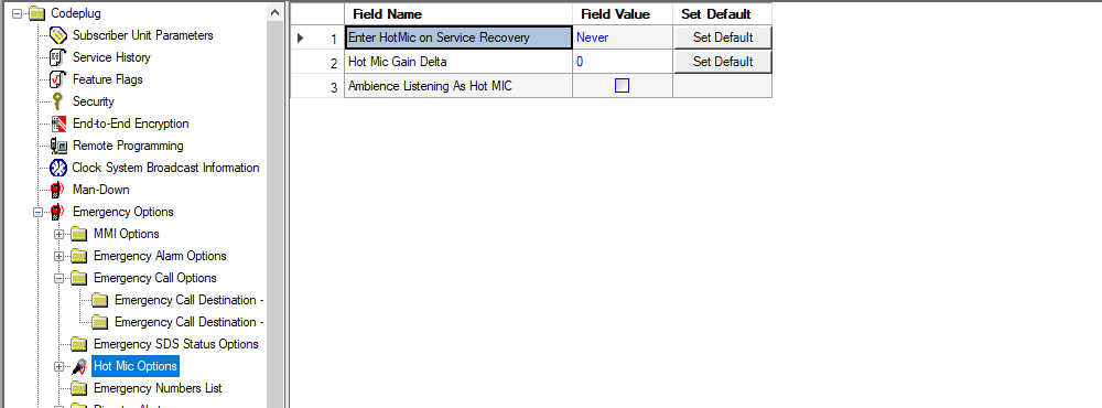
Under Emergency Options → Hot Mic Options, I set Enter HotMic on Service Recovery = Never, so restored coverage does not automatically restart Hot Mic. Hot Mic Gain Delta = 0 and Ambience Listening As Hot MIC stays off.
Then open Hot Mic Options → TMO. I enable TMO Group HotMic and disable TMO Private HotMic. The microphone can therefore remain open during a group emergency without PTT. Enable this only if that is the behaviour you want.
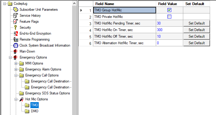
The screenshot’s 300 belongs to TMO HotMic On Timer, sec: five minutes of open microphone. My TMO HotMic Pending Timer = 30 s, TMO HotMic Off Timer = 10 s and TMO Alternation HotMic Timer = 0. Do not put 300 into Pending Timer, GPS Cycle or Max Data Age. Microphone duration and GPS reporting rate are independent.
17. Test GPS and APRS
- Save the edited file under a new name. File → Write Radio is sufficient for these normal CPS fields; GPS/emergency changes need no extra full LAB write.
- Read back and compare GPS Cycle, protocol, destination, triggers and emergency target.
- On the radio, check Location → Interface → On. Menu wording depends on radio language.
- With a suitable antenna and clear sky view, allow about 10–15 undisturbed minutes for a first GPS test. This is a test period, not a guaranteed time to fix. A window test is not a reliable comparison.
- Confirm current coordinates locally, register on TMO, wait for a normal LIP report, then check the location service/APRS.
- Agree any emergency test with the operator and affected participants first. Check alarm, voice target, optional Hot Mic and position report separately, then leave emergency mode.
| Observation | Next check |
|---|---|
| No valid coordinates | GPS enabled, correct cycle, sky view, antenna and GPS information page. An APRS address cannot replace these checks. |
| Coordinates but no network report | LIP/SDS, destination, initialisation, enabled trigger and network support. |
| Network report but no APRS | Network forwarding, subscriber mapping, APRS callsign and timestamps. |
| Missing GPS icon | Check “GPS Icon when No Fix Available” against actual position/fix status. |
| Emergency reaches an unexpected group | For Tactical, check the currently selected and attached group. |
Sources
Menus and field names were checked against my MTP850s, CPS and its help topics: Address Extension, Frequency List2, TMO Folders List, TMO Talkgroup List, Contact List, and Modifying a Codeplug Using an XML File. LAB-write behaviour refers to CPS Plus 07.90.00.77.
GPS and emergency sections use my CPS screenshots from 5 November 2026 and help for GPS Cycle, GPS Settings, LIP Configuration, LIP Triggers, Emergency Options and Hot Mic. Screenshots show my profile; confirm supported location/emergency functions with your network operator.
- Motorola TETRA CPS Plus: local help for the menus and tables listed above.
- Motorola MTP850s service manual and connector pinout
- tmo.services groups and contact lists
- Motorola MTP850 TETRA Product Information Manual, 68015000887-HC, for location protocols and emergency functions. Motorola documentation portal.